The Steam Turbine
by Sir CHARLES A. PARSONS, K.C.B.
Now as to the best speed of the blades, it will be easily seen that
in order to obtain as much power as possible from a given quentity of steam,
each row must work under appropriate conditions. This has been found by
experiment to require that the velocity of the blades relatively to the
guide blades shall be from one-half to three-quarters of the velocity of the
steam passing through them, or more accurately equal to one-half to
three-quarters of the velocity of issue from rest due to the drop of
pressure in guides or moving blades, for in the usual reaction turbine the
guides are identical with the moving blades.
The curve for efficiency in relation to the velocity ratio has a
fairly flat top, so that the speed of the turbine may be varied considerably
about that for maximum efficiency without materially affecting the result.
 In compound land turbines the efficiency of the initial rows is
about 60 per cent, and of the latter rows 75 to 85 per cent, and considering
the whole turbine, approximately 75 per cent of the energy in the steam is
delivered on to the shaft. The expansion curve of the steam les between the
adiabatic and isothermal curves, but nearer the former, because 75 per cent
is converted into work on the shaft and only 25 per cent is lost by friction
and eddies in the steam and therefore converted into heat.

In turbine design the expression of the velocity ratio between the
steam and blades may be represented by the integral of the square of the
velocity of each row through the turbine, and if, for instance, this
integral is numerically equal to 150,000,--a usual allowance for land
turbines,--then we know that, with a boiler pressure of 200 lbs. and a good
vacuum, the velocity of the blades will be a little over one half that of
the steam, and the turbine will be working close up to that speed which
gaives the maximum efficiency. In large marine turbines where weight and
space are of importance the integral may be
from 80,000 to 120,000 or more. With the first figure a loss of efficiency
of about 10 per cent below the highest attainable is accepted, and with the
latter figure the deficit is only about 3 per cent.
The construction of a suitable dynamo to run with the turbine
involved nearly as much trouble as the turbine itself: the chief features
were the adoption of very low magnetic densities in the armature core and
small diameters and means to resist the great centrifugal forces as shown in
 the views on page 18. The dynamo was also mounted in elastic bearings. Now
that the turbine has found its most suitable field in large powers to which
we always looked forward and as the speed of revolution has been
consequently reduced, elasticity in the bearings is less essential, and in
large land plants and in marine work rigid bearings are universal.
There are many forms of turbines on the market. It is only
necessary, however, for us here to consider the four chief types which
are:--
First, the compound reaction turbine with which we have been
dealing, representing over 90 per cent of all marine turbines in use in the
world, and about half the land turbines driving dynamos.
Second, the de Laval, which is only used for small powers.
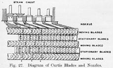
Third, the "multiple impulse, compounded" or Curtis, which has been
chiefly used on land, but which has been fitted in a few ships.
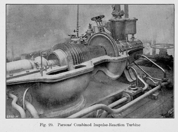
Lastly, a combination of the compound reaction type with one or more
"multiple impulse or Curtis elements" at the high-pressure end to replace
the reaction blading.
We may dismiss the other varieties as simply modifications of the
original types without possessing any originality or scientific interest.
Now let me further explain the multiple impulse type, and commence
by saying that it is the only substantial innovation in turbine practice
since the compound reaction and the de Laval turbines came into use. It was
proposed by Pilbrow in 1842, and first brought into successful operation by
Curtis in 1896. Some consideration should be given to it as involving
several characteristic points of difference from what has been said about
the compound reaction type. Curtis in the first place used the de Laval
divergent nozzle, and he also used compounding to the limited extent of only 5 to 9
 stages, as compared with 50 to 100 in the compound type. With these
provisos the same principles in the abstract as regards velocity ratio now
apply, and the steam issuing from the jets rebounds again and again between
the fixed and moving buckets at each velocity compounded stage: the best
velocity ratio in a four row multiple impulse is only one-seventh andthe
efficiency about 44 per cent, and therefore much lower than that of reaction
blading, which as we have stated is under favourable conditions 75 to 85 per
cent.
The advantages, however, to be derived from the use of some multiple
impulse elements at the commencement of the turbine are that because there
is very little loss in them from leakage, therefore in spite of their low
intrinsic efficiency, one or more multiple impulse wheels can in certain
cases usefully replace reaction blading. The explanation is that in
turbines of the compound reaction type of moderate power and slow speed of
revolution the blades are often very short at the commencement, and
 consequently there is in such cases excessive loss by leakage through the
clearance space, which brings the efficiency below that of impulse blading.
In most cases one multiple impulse wheel is preferred, followed by reaction
blading. Such impulse-reaction turbines are illustrated on pages 23 and 24.
When highly superheated steam is used the temperature is much
reduced by expansion in the jets and work done in the impulse wheel before
it passes to the main turbine casing.
The highest efficiency yet attained by land turbines has, however,
been with the pure compound reaction type of large size, where the high
pressure portion is contained in a separate casing of short length and great
rigidity, now made usually of steel. The working clearances can by this
arrangement be reduced to a minimum and the highest efficiency attained.
The first turbine imported into Germany in 1900, of 2000 H.P., was
on this principle, while the latest turbines are of 12,000 H.P., and
generate current for the Metropolitan Railway in London.

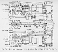
In marine work the same principle has been almost universal since
1896, when the original single turbine of the "Turbinia" was
replaced by three turbines in series (on the steam) on differnet shafts
(page 26), and it is adopted in all the largest liners and almost all large
war vessels. In marine work this division of the turbine has the additional
advantage that owing to the power being subdivided over three shafts,
smaller screws are admissible, and the speed of revolution may be increased
in the case of three turbines in series in the ratio of 1 to sqrt3.
Generally the turbines are place two in series, as in cross-channel boats,
the "Mauretaina" and "Lusitaina," torpedo craft, battleships, and cruisers
(page 27), or sometimes three in series (page 29) as in the liner "La
France" and the latest and largest Cunard liner now building. Four turbines
in series have been proposed, but have not as yet been constructed.
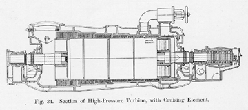
A war vessel in commission is working at reduced power for most of
the time, and on long voyages economy of fuel is of great importance. To
attain this end, additional turbines are fitted in front of the main full
power turbines. They are of small size, and
in separate casings, or they may form an integral portion of the main high
pressure turbine, which is then lengthened by the addition of the cruising
portion (page 30). They are partially by-passed as more power is required,
and at full speed they are entirely by-passed, or, when in separate casings,
are completely isolated from the steam supply by suitable valves, and are
generally connected to the condenser and rotate in vacuum, so that there is
no appreciable resistance to rotation. In some instances of modern naval
construction one or more multiple impulse wheels have constituted the
cruising element.
The Steam Turbine | Part I | Part III |