The Steam Turbine
by Sir CHARLES A. PARSONS, K.C.B.
THE STEAM TURBINE
In modern times the progress of science has been phenomenally rapid.
The old methods of research have given place to new. The almost
infinite complexity of things has been recognized and methods, based on a
co-ordination of data derived from accurate observation and tabulation of
facts, have proved most successful in unravelling the secrets of Nature; and
in this connection I cannot but allude to the work at the Cavendish
Laboratory and also to that at the Engineering Laboratory in Cambridge, and
tot he association of Professor Ewing with the early establishment of
records in steam consumption by the turbine.
 In the practical sphere of enginerring the same systematic research
is now followed, and the old rule of thumb methods have been discarded. The
discoveries and data made and tabulated by physicists, chemists, and
metallurgists, are eagerly sought by the engineer, and as far as possible
utilized by him in his designs. In many of the best equipped works, also, a
large amount of experimental research, directly bearing on the business, is
carried on by the staff.
The subject of our lecture today is the Steam Turbine, and it may be
interesting to mention that the work was initially commenced because
calculation showed that, from the known data, a successful steam turbine
ought to be capable of construction. The practical development of this
engine was thus commenced chiefly on the basis of the data of physicists,
and as giving some idea of the work involved in the investigation of the
problem of marine propulsion by turbines, I may say that about
24,000 £ was spent before an order was received. Had the system been a failure or
unsatisfactory, nearly the whole of this sum would have been lost.
Further, in order to prove the advantage of mechanical gearing of
turbines in mercantile and war vessels about 20,000 £ has been recently expended, and considerable financial risks have been undertaken
in relation to the first contracts.
With these preliminary remarks I now come to the subject of our
lecture.

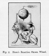
The first turbine of which there is any record was made by Hero of
Alexandria, 2,000 years ago, and it is probably obvious to most persons that
some power can be obtained from a jet of steam either by the reaction of the
jet itself, like a rocket or by its impact on some kind of paddle wheel.
About the year 1837 several reaction steam wheels were made by Avery at
Syracuse, New York, and by Wilson at Greenock, for driving circular saws and
cotton gins. Fig. 3 shows the rotor of Avery's machine: steam is
 introduced into it through a hollow shaft, and, by the reaction of the jets
at the extremities, causes rotation. The rotor was 5 feet across, and the
speed 880 feet per second. These wheels were inefficient, and it is not so
obvious that an economical engine could be made on this principle. In the
year 1888 Dr de Laval of Stockholm undertook the problem with a considerable
mearsure of success. He caused the steam to issue from a trumpet-shaped
jet, so that the energy of expansion might be utilized in giving velocity
to the steam. Recent experiments have shown that in such
jets about 80 per cent of the whole of the available energy in the steam is
converted into kinetic energy of velocity in a straight line, the velocity
attained into a vacuum being about 4,000 feet per second. Dr de Laval
caused the steam to impinge on a paddle wheel made of the strongest steel,
which revolved at the highest speed consistent with safety, or about half
the velocity of the modern rifle bullet, for the centrifugal forces are
enormous. Unfortunately, materials are not strong enough for the purpose,
and the permissible speed of the wheel can only reach about two-thirds fo
that necessary for good economy, as I shall presetly explain. Dr de Laval
also introduced spiral helical gearing for reducing the enormous speed of
rotation of his wheel (which needed to be kept of small diameter because of
skin fraction losses) to the ordinary speeds of things to be driven, and I
shall allude to this gear later as a mechanism likely to play a very
important part generally in future turbine developments.
In 1884 or four years previously, I dealt with the turbine problem
in a different way. It seemed to me that moderate surface volocites and
speeds of rotation were essential if the turbine motor was to receive general
acceptance as a prime mover. I therefore decided to split up the fall in pressure
of the steam into small fractional expansions over a large number of turbines in series,
so that the velocity of the steam nowhere should be great. Consequently, as
we shall see later, a moderate speed of turbine suffices for the highest
economy. This principle of compounding turbines in series is now
universally used in all except very small engines, where economy in steam is
of secondary importance. The arrangement of small falls in pressure at each
turbine also appeared to me to be surer to give a high efficiency, because
the steam flowed practically in a non-expansive manner through each
individual turbine, and consequently in an analogous way to water in
hydraulic turbines whose high efficiency at that date had been proved by
accurate tests.
 I was also anxious to avoid the well-known cutting action on metal
of steam at high velocity.
The close analogy between the laws for the flow of steam and water
under small differences of pressure have been confirmed by experment, and
the usual formula of velocity =
  gh,
where h is the hydraulic head, gives the velocity of issue from a jet for
steam with small heads and also for water, and I shall presently follow this
part of the subject furgher in dealing with the design of turbines. Having
decided on the compound principle it was necessary to commence with small
units at first; and thus, notwithstanding the compounding, the speed of
revolutions though much reduced was still rather high.

The compound steam turbine of 10 horse power (page 7) ran at 18,000
revolutions per minute, and had slightly elastic bearings to allow it to
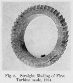
rotate about its dynamic or principal axis. The turbine teeth or blades
were like a cog wheel, set at an angle and sharpened at the front edges, and
the guide blades were similar. These are shown in Fig. 6 on the next page.
Gradually the form of the blades was improved as a result of
experiments and some of these are shown on page 10. Curved blades with
thickened backs were introduced. The blades were cut off to length from
brass, hard rolled and drown to the required section, and inserted into a
groove with distance pieces between and caulked up tightly.


Dummy labyrinth packings of various types were introduced. Two of these are
illustrated in Figs. 16 and 17 on page 10. The design was improved,
generally, so as to reduce steam leakages and to provide for greater ratios
of expansion.
The diagrams on page 11 show the latest method of forming segments
of blades by stringing blades and distance pieces alternately on wire within
a groove formed of two castings bolted together and corresponding to the
 groove of the turbine rotor or casing. The engraving on page 12 illustrates
these segments being made. The view on page 15 shows segments being fitted
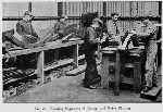 in a rotor.
I have said that steam behaves almost like an incompressible fluid
in each turbine of the series, but because of its elasticity its volume
gradually increases with the succession of small falls of pressure, and the
succeeding turbines consequently are made larger and larger. This
enlargement is secured in three ways: (1) by increasing the height of
blade, (2) by increasing the diameter of the succeeding drums, and (3) by
altering the angles and openings between the blades. All three methods are
generally adopted (page 17) to accommodate the expanding volume of the steam
which in a condensing turbine reaches one hundredfold or more before it
issues from the last blades to the condenser.
The Steam Turbine | Part II |